Debug log capture for communication modules
Edit
Overview
This document describes how to retrieve the debug log of Wi-Fi modules.
If there are some unknown errors when using Gizwits Wi-Fi modules for debugging, you can follow the steps below to collect the corresponding log information and provide it to the Gizwits technical team to identify the issues.
How to collect the Wi-Fi module log
1. Get ESP8266 GAgent log
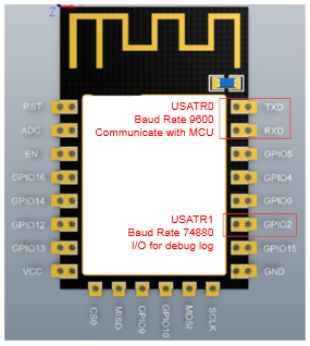
The following steps take Espressif ESP-12S as an example:
Step 1: According to the pin layout of Espressif ESP-12S, connect the GPIO2 (UART1_TXD) (for debug log output) shown in the figure to the PC through a USB-to-TTL converter, and make a note of the corresponding COM port.
Step 2: Download the Youshan serial port debug tool.
Download address: http://pan.baidu.com/s/1o8ER3yM
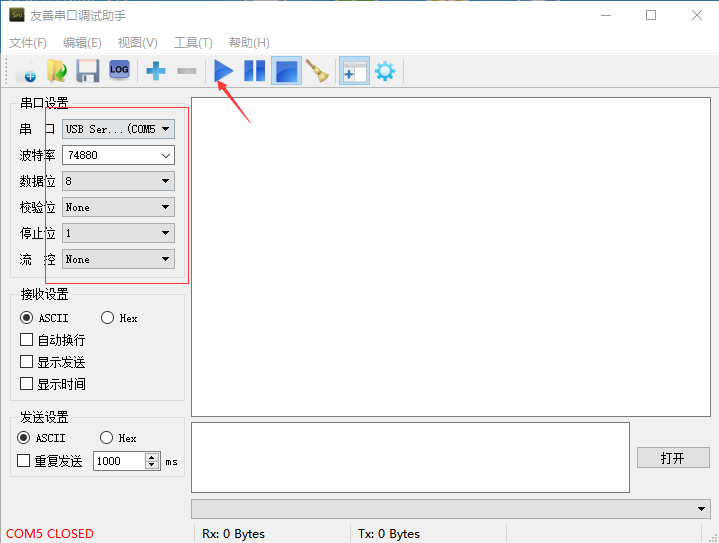
After downloading and unpacking, install and start the software. Select the COM port as noted in step 1 as shown in the following figure, set the Baud rate to 74880, then choose ASCII, and click the Start button.
Step 3: At this time, the log contents will appear in the blank area of the serial port debug tool.
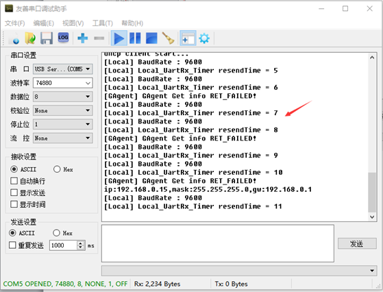
Step 4: Select all the log contents and save them in a txt file. Then send the file to the Gizwits FAE team.
2. Get High-Flying LPB100 GAgent log
Step 1: According to the pin layout of High-Flying LPB100, connect the Pin 8 (UART1_TXD) (for debug log output) shown in the figure to the PC through a USB-to-TTL converter, and make a note of the corresponding COM port.
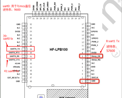
For step 2-4, refer to the corresponding steps listed in section 1. Furthermore, set the Baud rate to 57600.
3. Get High-Flying LPB120 GAgent log
Step 1: According to the pin layout of High-Flying LPB120, connect the Pin 26 (UART1_TXD) (for debug log output) shown in the figure to the PC through a USB-to-TTL converter, and make a note of the corresponding COM port.
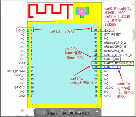
For step 2-4, refer to the corresponding steps listed in section 1. Furthermore, set the Baud rate to 115200.
Step 1: According to the pin layout of Fibocom G510, connect the Pin 19 (UART1_TXD) (for debug log output) shown in the figure to the PC through a USB-to-TTL converter, and make a note of the corresponding COM port.
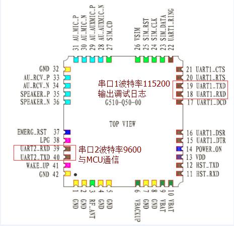
For step 2-4, refer to the corresponding steps listed in section 1. Furthermore, set the Baud rate to 115200.
Note: It is recommended to use the voltage of 4V for G510 module power supply.