In order to lower the development barrier, shorten the development cycle, and reduce the development investment, Gizwits has rolled out Gizwits MCU Code Auto-Generator, which generates the device-side code for the corresponding product based on Data Points defined for the product.
The automatically generated MCU code implements the packet encapsulation and parsing of the Gizwits communication protocol, the conversion logic of sensor data and communication data. All of these functions are integrated into a simple API set. When the device receives data from the cloud or the App, the program converts the data into corresponding events and notifies the application layer. You only needs to add the sensor control functions to the corresponding event handlers to complete the product development.
With the automatically generated code, you don’t have to deal with protocol-related issues, and focus on the core functional development of the product, which allows you to save time and effort.
The standalone MCU scheme supports the STM32F103C8x platform by default. For other MCU chips, you can port the generated Common Platform Edition of MCU SDK to the qualified platform to implement the various functions provided by Gizwits. This document will focus on the porting to the Common Platform Edition of MCU SDK.
2. How to use Gizwits MCU Code Auto-Generator for the Common Platform Edition of MCU SDK?
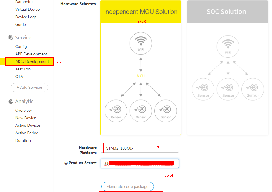
After defining a product in Gizwits IoT Cloud, click “MCU Development” in the left navigation pane, and choose the standalone MCU scheme for the hardware scheme. In the hardware platform drop-down list, select Other platforms. Then click “Generate Code” and wait to download the generated code package.
After downloading the code package, unpack it.
3. Know before you go
Before the porting, you must ensure that the target hardware platform meets the following requirements:
A. The platform supports two serial ports (at least one), one for data transmission and reception with the Wi-Fi module (required), and the other for debugging information printing (the former port can be reused for this purpose).
B. The platform supports the timer function (with 1ms accuracy).
C. The platform supports at least 2K RAM (the ring buffer size can be adjusted to solve this problem, but it is likely to induce abnormalities when processing the data protocol).
Note: Set the ring buffer here: Gizwits\gizwits_protocol.h
In the above code snippet, MAX_PACKAGE_LEN = 950, that is, the size of the ring buffer is 950*2 = 1900 bytes. Here you can adjust the RAM usage of the program.
Porting instructions
1. Introduction to the related files
1). gizwits_product.c
This file contains product-related processing functions such as gizwitsEventProcess().
2). gizwits_product.h
This file is the header file for gizwits_product.c, which contains macro definitions of HARDWARE_VERSION, SOFTWARE_VERSION etc.
3). gizwits_protocol.c
This file is for function definitions of the SDK API.
4). gizwits_protocol.h
This file is the header file of gizwits_protocol.c, which contains the function declarations of the SDK API.
5). Other files
a) User/main.c
The file is where the MCU program entry point is located. The entry point is main(void) function.
2. Introduction to the related API
void gizwitsInit (void)
The initialization API for the Gizwits protocol.
You can call the API to accomplish the Gizwits protocol-related initialization (including protocol-related timers and serial port initialization).
void gizwitsSetMode (uint8_t mode)
The parameter mode has three choices of 0, 1, and 2, and other input is invalid.
When the parameter is set to 0, it is used for restoring manufacture defaults, which will clear all settings and restore the module to the factory defaults.
When the parameter is set to 1 or 2, it is used for SoftAP and AirLink mode switch. 1 for entering the SoftAP mode, and 2 for entering the AirLink mode.
void gizwitsHandle(dataPoint_t *dataPoint)
The parameter dataPoint is the device Data Point.
This function completes the processing of the corresponding protocol data, that is, the related operations of data reporting.
User data processing function, including Wi-Fi status update events and control-type events.
a). Wi-Fi status update events
The events whose name begins with WIFI_ are the Wi-Fi status update events. The parameter data is valid only when the event name is WIFI_RSSI, and its value is RSSI value, its data type is uint8_t, and its value range is 0~7.
b). Control-type events
They are related to the Data Points. This version of the code will print the relevant event information and the relevant values. You only need to implement the specific execution of the command.
3. Code structure
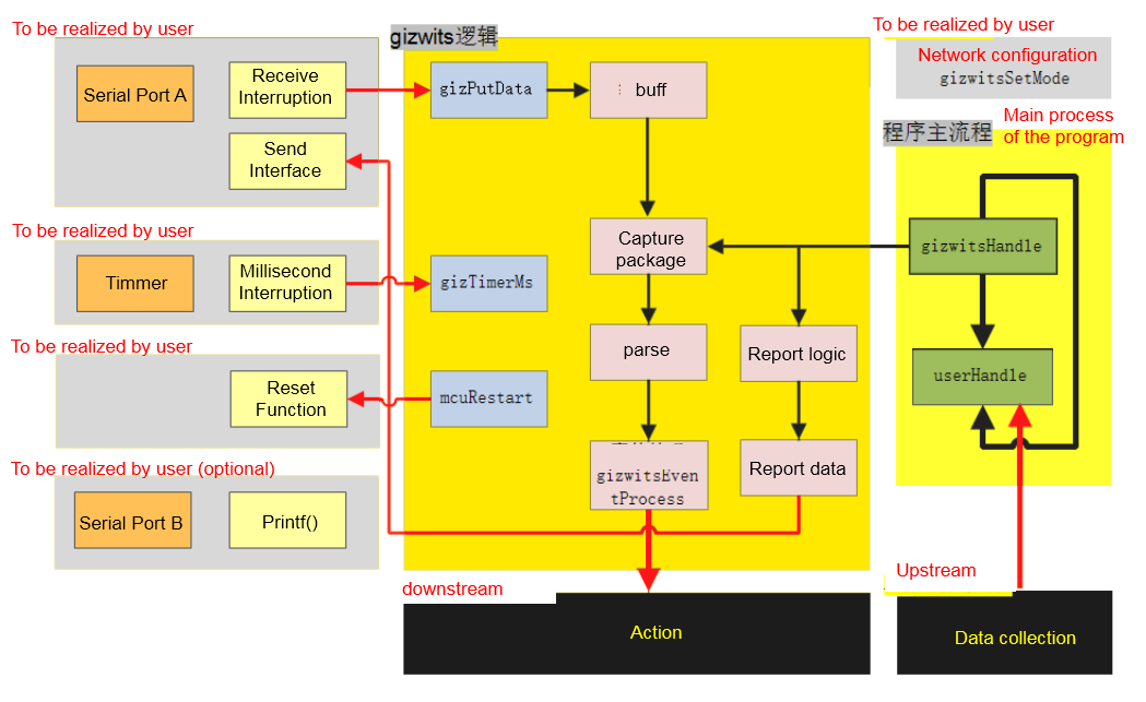
Gizwits MCU Code Auto-Generator has produced the corresponding Gizwits serial protocol layer code according to the user-defined product Data Points, and you need to port the code into your own project to complete the device connection as shown below:
The protocol logic and the main program flow in the green blocks of the above figure have been implemented for you. The blocks marked with the yellow text in the figure is to be implemented. The porting process is composed of the following steps:
a. Set up a minimum platform project (required).
b. Implement serial port driver (required): including communication and printing functions.
c. Implement timer driver (required).
d. Implement the chip reset function (optional).
e. Implement application layer logic (required): including uplink processing, downlink processing and network access configuration, etc.
Porting steps
Below we take the MSP430 platform as an example to introduce the porting steps.
1. Set up a minimum platform project (required)
First, set up the minimum project for the target platform. Take MSP430 as an example. We import the source files responsible for the communication protocol processing (all files in the Gizwits directory) into the project, and consolidate the sample main.c file under the User directory into the project as follows:
The standalone MCU scheme requires you to implement a serial port for data communication between the device MCU and the WIFI module. You first need to implement the interrupt handler function for serial receive UART_IRQ_FUN (For MSP430 platform, it is USCI0RX_ISR), which calls gizPutData() function to receive the serial port data and write it to the protocol layer data buffer.
The following takes the MSP430 platform as an example. In this example, USCI0 is used to communicate with the module. The serial port initialization is implemented as follows:
1
2
3
4
5
6
7
8
9
10
11
12
13
14
15
16
void Sys_Init(void)
{
	//stop watchdog timer

    WDTCTL = WDTPW + WDTHOLD;

	//set clock

    InitClock();

	//set serial port -9600bps

    serial_init(9600);

    cio_printf(" Start system \n"; );
}
The interrupt handler function for serial receive is implemented as follow:
__interruptvoid USCI0RX_ISR(void) { while (!(IFG2&UCA0TXIFG)); // USCI_A0 TX buffer ready?
gizPutData((uint8_t *)&UCA0RXBUF,1);
return; }
In addition, you need to implement the function for serial transmit, which is called by the uartWrite() function to accomplish the device data transmission. It is important to note that the uartWrite() function in the gizwits_product.c file is a pseudo-function. You need to complete uartWrite() according to the function for serial transmit. Please pay attention to the relevant comment as following to prevent errors from occurring.
for (i = 0; i < len; i++) { serial_send_blocking(buf[i]);
// implement the function for serial transmit, which sends buf[i] to the module
if (i >= 2 && buf[i] == 0xFF) {
// implement the function for serial transmit, which sends 0x55 to the module
serial_send_blocking(0x55); } }
return len; }
Note the conditional statement for 0x55 in the example, that is, every time 0xFF appears, 0x55 is appended to it.
If you want to print debugging log, the GIZWITS_LOG function is needed to be implemented, and just update the corresponding macro definition in gizwits_protocol.h, as follows:
1
#define GIZWITS_LOG cio_printf // log print
3. Implement timer driver
The protocol layer uses a system time in milliseconds. Therefore, you are required to implement a millisecond timer (It must have an accuracy of 1ms. If it is inaccurate, it will affect the processing of retransmission timeout, regular reporting, etc.) and the interrupt handler function TIMER_IRQ_FUN (For MSP430 platform, it is Timer_A), which calls gizTimerMs () to accomplish the maintenance of the protocol layer system time.
The following takes the MSP430 platform as an example, where Timer_A is used to implement the system time maintenance and the timer initialization as follows:
BCSCTL3 |= LFXT1S_2; // set LFXT1 to the VLO @ 12kHz
CCTL0 |= CCIE; // set the capture/compare control register, CCIE=0x0010, capture/compare interrupt enable
CCR0 = 12; // set the capture/compare control register. The initial value is 12000, which is equivalent to 1s and 12 likewise is equivalent to 1ms.
TA0CTL = TASSEL_1 + TACLR + MC_1; // set the timer A control register,
//set serial port-9600bps
serial _init(9600);
cio_printf("Start system \n"); }
The interrupt handler function is implemented as follows:
1
2
3
4
5
6
#pragma vector=TIMER0_A0_VECTOR // fixed format

__interruptvoid Timer_A (void) // Timer A's CC0 interrupt handler must have a return type of void
{
 	gizTimerMs();
}
4. Implement chip reset function
According to the serial protocol document, the module can send a command to reset the device MCU, so you need to implement the mcuRestart() function in gizwits_product.c. The following takes the MSP430 platform as an example.
At this point, the porting is completed, and the subsequent operations of the network access configuration, uplink processing and downlink processing belong to the application logic development.
5. Implement application layer logic (required)
5.1 Downlink processing
The Data Point operation will be converted into a Data Point event, and you only need to do specific processing under the corresponding event of gizwitsEventProcess() in the gizwits_product.c file.
The following takes the MSP430 platform to implement the LED control as an example.
if (0x01 == currentDataPoint.valueLED_ONOFF) { //user handle
P1OUT |= BIT6; } else { //user handle
P1OUT &= ~BIT6; }
break;
//to do
default: break; } }
return 0; }
5.2 Uplink processing
The project source code implements the sensor data collection in userHandle() of Gizwits\gizwits_product.c. A while loop loops through the userHandle() function. In principle, you only need to care about how to collect the sensor data.
In particular, the default while loop execution speed is fast, and you can adjust the data collection period and the interface implementation location according to different needs to prevent unnecessary issues caused by the fast sensor data collection (see STM32 for details).
The MSP430 platform is used below, taking the state of the lamp as an example (the operation code for the read-only Data Point is automatically generated by the cloud), as follows:
1 2 3 4 5 6 7 8 9 10 11 12 13 14 15 16
/**
* user data collection
* Here you need to implement the collection of all sensor data except the writable Data Points, and can customize the acquisition frequency and design data filtering algorithm.
According to the serial protocol document, the MCU can send commands to the module to enter the corresponding configuration mode by calling the gizwitsSetMode function (in gizwits_protocol.c) through the corresponding operation (such as key press). The function is as follows:
1
2
3
4
5
6
7
8
9
10
11
12
13
/**
* @brief Wi-Fi configuration function
* You can call the function to enable the Wi-Fi module to enter the corresponding configuration mode or reset module.
You can get the Wi-Fi state in gizwitsEventProcess() of gizwits_product.c and do the corresponding logic processing.
The following takes the MSP430 platform as an example to add a logic: When the Wi-Fi module successfully connects to the router, turn off the LED light. The code example is as follows:
1
2
3
case WIFI_CON_ROUTER:
		P1OUT &= ~BIT6;
break;
Support
For individual developers
Gokit is free, but only a limited number are available for individual developers. Register in our forum or follow our official WeChat to request for provision.