Getting started with I-CUBE-GIZWITS IoT cloud software expansion for STM32Cube
Introduction
This user manual describes the content of the STM32Cube software expansion package for the GIZWITS®
IoT cloud platform.
The GIZWITS® IoT cloud software expansion package (I-CUBE-GIZWITS) for STM32Cube provides application examples that connect STMicroelectronics boards to the GIZWITS® IoT cloud platform. It uses the GIZWITS® GAgent library which is compiled and running onthe STM32 device.
I-CUBE-GIZWITS runs on the B-L475E-IOT01 board.
Implementation examples are included for device-to-cloud telemetry reporting ,cloud-to-device messages for notifications to the connected devices, device pre-authorization and firmware Over The Air (OTA) upgrade.
I-CUBE-GIZWITS offers the following features:
• Ready to run firmware example using Wi-Fi® to support quick evaluation and development of GIZWITS® GAgent device applications
• Board configuration interface
• Wi-Fi® connection
• Connection to the GIZWITS® IoT cloud platform
• The B-L475E-IOT01 board measures and can report any one of the following values:
– Humidity
– Temperature
– 3D acceleration
• Commands sent from mobile App to control the user on board LED, to turn it On/Off
• Device pre-authorization
• Firmware over the air upgrading (OTA)
The I-CUBE-GIZWITS package for the GIZWITS® IoT cloud platform runs on STM32 32-bit microcontrollers based on the Arm® Cortex®-M processor.

Table1 presents the definition of acronyms that are relevant for a better understanding of thisdocument.
Table 1. List of acronyms
| Term |
Definition |
| API |
Application programming interface |
| BSP |
Board support package |
| CA |
Certification authority |
| DHCP |
Dynamichostconfiguration protocol |
| DNS |
Domain name server |
| HAL |
Hardware abstraction layer |
| IDE |
Integrated developmentenvironment |
| IoT |
Internet ofthings |
| IP |
Internet protocol |
| LED |
Light-emitting diode |
| OTA |
Over the Air firmware upgrade |
| RTC |
Real-time clock |
| UART |
Universal asynchronous receiver/transmitter |
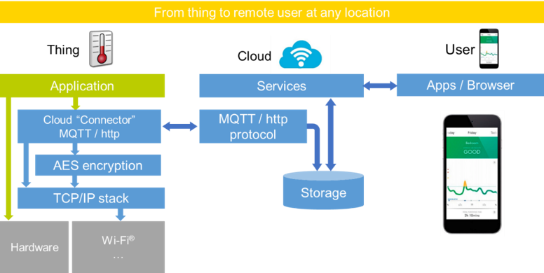
This chapter introduces the GIZWITS® IoT cloudplatform.
The I-CUBE-GIZWITS package implements the GIZWITS® GAgent client library which allows the board to securely connect to the GIZWITS® IoT cloud platform.
GAgent is GIZWITS's hardware connectivity with the embedded system firmware that can operate in STM32. Devices access GIZWITS® IoT Cloud platform through the GAgent. GAgent provides the communication protocol between cloud and MCU, so that, according to the protocol, developers can realize the communication between MCU and GAgent.
A user can connect to the cloud with a smartphone and haveaccess to the information provided by the board at any time and from any location.
Figure 1 presents the GIZWITS®
IoT cloud ecosystem targeted by the I-CUBE-GIZWITS package.
Figure 1. GIZWITS® IoT cloud ecosystem
3.Package description
This chapter details the I-CUBE-GIZWITS package content and the way to use it.
3.1 General description
The I-CUBE-GIZWITS package provides a GIZWITS® GAgent stack middleware for STM32 microcontrollers.
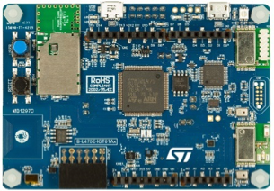
It is built to run on the B-L475E-IOT01 boards and connects to the Internet through the on-board network interface:
• B-L475E-IOT01 supports Wi-Fi® connectivity with an on-board Inventek® WiFi module.This board is equipped with a set of sensors able to report humidity,temperature,3D-axis magneticdata,3D accelerations,3D gyroscope data,atmospheric pressure,proximity and gesture detection(I-CUBE-GIZWITS does not use the gesture detection capability).
Figure 2. B-L475E-IOT01A board
The package is split into the following software components:
• Client libraries and samples for connecting to GIZWITS® IoT cloud platform.
• FreeRTOS™
• Wi-Fi® drivers
• Sensor drivers for the B-L475E-IOT01 board
• STM32L4 Series HAL
• GIZWITS® application examples
The software is provided as a zip archive containing source code. The following integrated development environments are supported:
• IAR Embedded Workbench® for Arm®(EWARM)
• Keil® Microcontroller Development Kit(MDK-ARM)
• System Workbench for STM32
Note: refer to the release note available in the package root folder for information about the IDE versions supported.
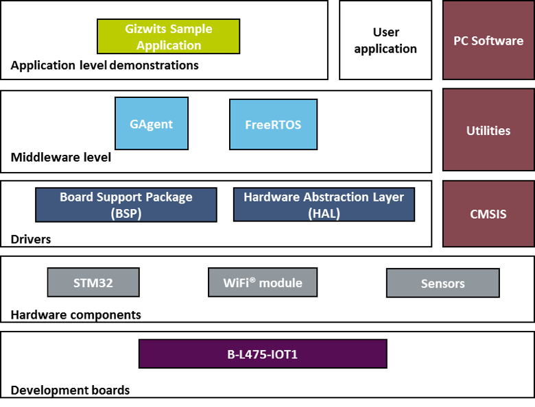
3.2 Architecture
This section describes the software components of the I-CUBE-GIZWITS package.
The I-CUBE-GIZWITS software is an expansion for the STM32Cube.Its main features and characteristics are:
• Fully compliant with STM32Cube architecture
• Expands STM32Cube in order to enable the development of applications accessing and using the GIZWITS® IoT cloud platform
• Based on the STM32Cube HAL,which is the hardware abstraction layer for STM32 microcontrollers
The software components used by the application software to access and use the GIZWITS® IoT cloud platform are the following:
- STM32CubeHAL
The HAL driver layer provides a generic multi-instance simple set of APIs(application programming interfaces)to interact with the upper layers(application,librariesand stacks).
It is composed of generic and extension APIs.It is directly built around a generic architecture and allows the layers that are built upon,such as the middleware layer,to implement their functionalities without dependencies on the specific hardware configuration for a given microcontroller unit(MCU).
This structure improves the library code reusability and guarantees an easy portability onto other devices.
- Boardsupportpackage(BSP)
The software package needs to support the peripherals on the STM32 boards apart from the MCU.This software is included in the board support package(BSP).This is a limited set of APIs which provides a programming interface for certain board specific peripherals such as the LED and the user button.
GIZWITS® GAgent client middleware
FreeRTOS™
It is a real-time operating system required for simulating the Linux environment that was originally used to develop the GAgent client stack and GIZWITS application.
Figure 3. I-CUBE-GIZWITS software architecture
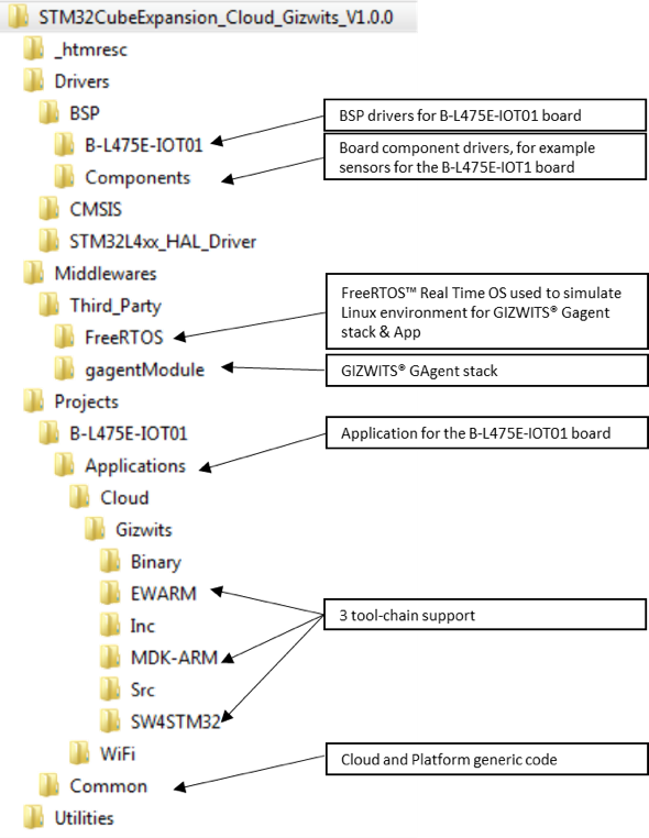
3.3 Folderstructure
Figure 4 presents the folder structure of the I-CUBE-GIZWITS package.
3.4 B-L475E-IOT01boardsensors
The sensors that are present on the board that can be used by the sample application are:
• Capacitive digital sensor for relative humidity and temperature(HTS221)
• High-performance 3-axis magnetometer(LIS3MDL)
• 3D accelerometer and 3D gyroscope(LSM6DSL)
• 260-1260 hPa absolute digital output barometer(LPS22HB)
• Proximity sensor(VL53L0X)
For the application example, only the data of humidity, temperature and 3-axis accelerometer has been selected and sent back to the cloud.
3.5 Wi-Fi® components
The Wi-Fi® software is split over Drivers/BSP/Components for the module specific software and over Projects/<board>/WiFi for I/O operations and for the Wi-Fi® module abstraction.
The Inventek Wi-Fi firmware version should be "ISM43362_M3G_L44_SPI_C3.5.2.5.STM" or later. More details about how to update the Inventek Wi-Fi firmware of B-L475E-IOT01 board can be found in the section of "utilities" at the following link, _https://www.st.com/content/st_com/en/products/evaluation-tools/product-evaluation-tools/mcu-eval-tools/stm32-mcu-eval-tools/stm32-mcu-discovery-kits/b-l475e-iot01a.html_.
The reset push-button(black) is used to reset the board at any time.This action makes the board reboot.
The user push-button(blue) is used in the following cases:
• To configure the Wi-Fi® access point credentials.This can be done from the time the board starts up and up to five seconds after that.
The application configures and manages the user button via the board support package (BSP) functions. The BSP functions are in the Drivers\BSP\<boardname> directory.
When using the BSP button functions with the BUTTON_USER value, the application does not take into account the way this button is connected from a hardware standpoint for a given platform. The mapping is handled by the BSP.
3.8 UserLED
The configuration of the user LED that is used by the applications is done via the board support package (BSP) functions.
The BSP functions are under the Drivers\BSP\<boardname> directory.
Using the BSP button functions with the LED_GREEN value, the application does not take into account the way the LED is mapped for a given platform. The mapping is handled by the BSP.
The behavior On/Off of user LED has been selected to be used for monitoring the commanding messages from GIZWITS mobile App.
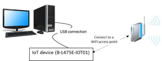
4.Hardware and software environment setup
To set up the hardware and software environment, the supported board must be plugged into a personal computer via a USB cable. This connection with the PC allows the user to:
• Flash the board
• Store the Wi-Fi® AP credentials
• Interact with the board via a UART console
• Debug
The B-L475E-IOT01 must be connected to a Wi-Fi® access point as illustrated in Figure 5.
Figure 5. Hardware and software setup environment
The prerequisites for running the examples are:
• A Wi-Fi® access point, with a transparent Internet connectivity meaning that neither a proxy, nor a firewall are blocking the outgoing traffic. It has to run a DHCP server delivering the IP and DNS configuration to the board.
• A development PC for building the application, programming through ST-Link, and running the virtual console.
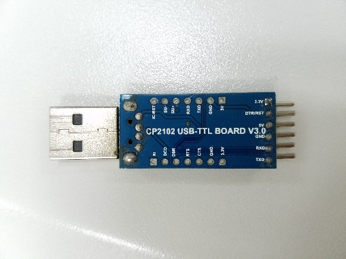
• A USB-TTL (USB to serial port transmission) board used for the pre-authorization of client board. Showed in Figure 6.
• A GIZWITS® account. Once registered a Product Key and Product secret for GIZWITS® IoT services will be provided.
To register and create an account, go to https://accounts.gizwits.com/en/register/
Figure 6. USB TTL Board
5.Interacting with the boards
A serial terminal is required to:
• Configure the board
• Display locally the received GIZWITS® IoT cloud-to-device messages
The example in this document is illustrated with the use of Tera Term. Any other similar tool can be used instead.
• Determine the STM32 ST-LINK Virtual COM port used on the PC for the Discovery board. On a Windows® PC, open the Device Manager.
• Open a virtual terminal on the PC and connect it to the above virtual COM port.
A Tera Term initialization script is provided in the package utility directory (refer to Figure 3). This script sets the correct parameters. To use it, open Tera Term, select Setup and then restore setup.
Note:
The information provided below in this chapter can be used to configure the UART terminal as an alternative to using the Tera Term initialization script.
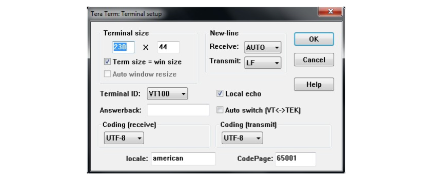
Terminal setup is illustrated in Figure 7, which shows the terminal setup and the New-line recommended parameters.
The virtual terminal New-line transmit configuration must be set to LineFeed (\n or LF) in order to allow copy-paste from UNIX type text files. The Local echo option makes copy- paste visible on the console.
Figure 7. Terminal Setup
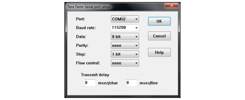
The serial port must be configured with:
• COM port number
• 115200 baud rate
• 8-bit data
• Parity none
• 1 stop bit
• No flow control
Serial port setup is illustrated in Figure 8.
Figure 8. Serial port setup
Once the UART terminal and the serial port are set up, press the board reset button (black). Follow the indications on the UART terminal to upload Wi-Fi® and GIZWITS® data. Those data remain in Flash and are reused the next time.
6.Application example
This section introduces how to register and log on the GIZWITS® IoT cloud platform, and how to use the GIZWITS® client application from the I-CUBE-GIZWITS package.
6.1 Applicationdescription
The GIZWITS® sample application illustrates the various way for a device to interact with the GIZWITZ® IoT hub, using the GIZWITS® GAgent stack on the device.
The application connects to the GIZWITZ® IoT hub thanks to the credential provided by the user in the code.
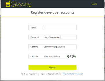
6.2 GIZWITS® IoT account creation
Toregister and create an account,goto:https://accounts.gizwits.com/en/register/
Figure 9. GIZWITS account creation
Once an account has been created:
- Create a new product.
- Select "WiFi/Cellular" solution.
- Give it a name, select the type of node, and the Product Key and Product Secret will be generated.
- Then select "Save"
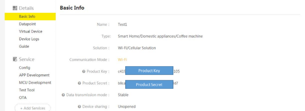
Figure 10. Product creation
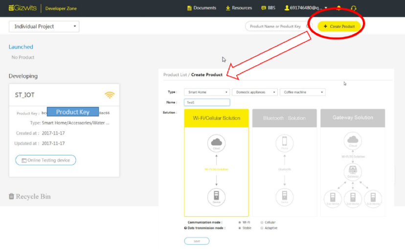
Figure 11. Product Secret generation
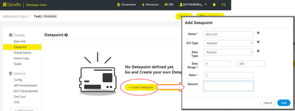
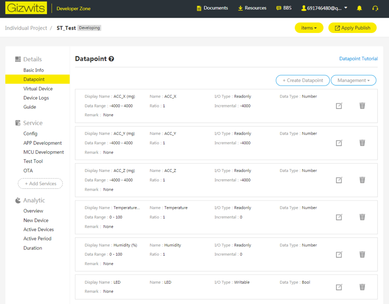
Create the datapoint by specifying its name, I/O Type, Data Type, Range and Steps (ratio). The datapoint set and used in this example application is showed in Figure 12.
Figure 12. Datapoint creation
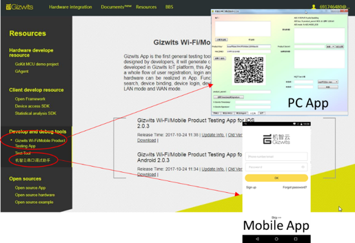
Go to the Resources page to:
- Download the GIZWITS PC application that generates a QR code
- Download the GIZWITS mobile app
- Download the GIZWITS PC application which is used for pre-
Figure 13. GIZWITS PC and Mobile app
6.4 Applicationbuildandflash
Caution: Before opening the project with any tool chain, make sure that the folder installation path is not too deep since the tool chain may report errors after the build otherwise.
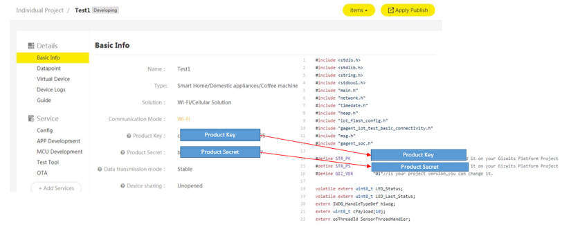
Enter the Product Key and Product Secret at the specified position gagent_iot_test_basic_connectivity.c which is located "\Projects\Common\Gizwits\Src\ "
Figure 14. Product Key and Product Secret provisioning
Open and build the project with one of the supported development tool chains (see the release note for detailed information about the version requirements).
Program the firmware on the STM32 board: you can copy (or drag and drop) the generated bin file to the USB mass storage location created when you plug the STM32 board to your PC.
Alternatively, you can program the STM32 board directly through one of the supported development tool chains.
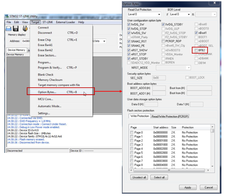
Note: In the case of B-L475E-IOT01 using, because of the existence of dual flash banks the user must make sure that the BFB2 option byte bit is in reset status in order to switch the booting bank to flash bank 1 before manually program the firmware on the board. This can be done by STM32 ST-LINK Utility which is a free software in www.st.com. The configuration in STM32 ST-LINK Utility is showed in Figure 15.
Figure 15. Configure STM32 ST-LINK Utility about BFB2
6.5 Application first launch
- Each product (like the one created at the beginning of section 6.3) has the capability of 10 free connected devices. If the number of devices under this product exceeds 10, the exceeding devices have to be activated by a pre-authorization process at the first launch. In this case, a USB-TTL (as Figure 6) should be connected to the PC (as Figure 16). The port connected with the grey wire is UART_RX, which should be connected to the UART_TX port of USB-TTL board. The other port has the opposite usage (TX to RX).
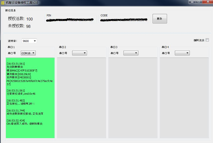
At the PC end, launch GIZWITS pre-authorization software, and set the port information. Make sure that the communication of PC to the Internet is OK and not blocked by a firewall. To obtain the PIN and CODE in this PC software, contact GIZWITS at https://dev.gizwits.com/en/developer/product/.
The pre-authorization process is only needed for the first time of accessing GIZWITS server for one given board. Once succeed (showed in Figure 17), the pre-authorization information will be saved into the flash so there is no need to do it for the second time on this board.
But if a full flash bank erasing procedure is done, the pre-authorization should be processed again.
Figure 16. Connection during pre-authorization
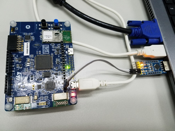
Figure 17. Pre-authorization software at PC end
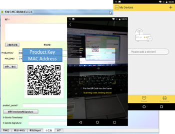
- Launch the GIZWITZ mobile app and scan the QR code generated from the GIZWITS PC application. The MAC address can be retrieved at the beginning, after system boot (as in step 4).
Figure 18. Launching GIZWITS mobile app
3.The board must be connected to a PC through USB (ST-LINK USB port). Open the console through a serial terminal emulator (such as Tera Term), select the ST-LINK COM port of the board, and configure it with:
– 8N1, 115200 bauds, no HW flow control
– Line endings set to LF
For more details, see Chapter 5: Interacting with the boards.
4.After the system boot up,entertheWi-Fi configuration (SSID,encryptionmodeandpassword) via theconsole. If successfully connected to the WIFI access point, some information like MAC address and IP address will be showed as Figure 19.
Figure 19. WiFi connection information input
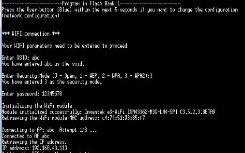
Note: After the parameters are configured, it is possible to change Wi-Fi network configuration by restarting the board and pressing User button (blue button) just after boot.
6.6 Application runtime
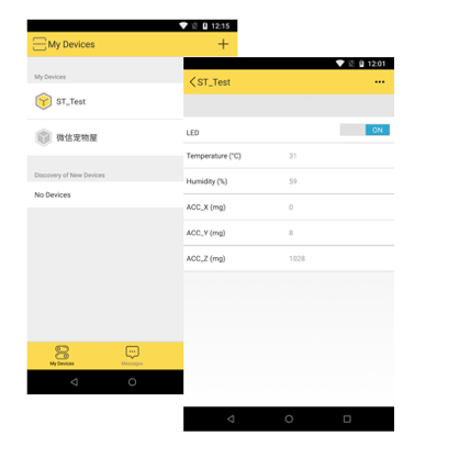
Once the connection to GIZWITS IoT cloud is established, the board will keep publishing the data from the sensors and LED to the cloud. The GIZWITS mobile app will then display the value of sensors and the status of LED on the mobile phone.
Figure 20. Device to Cloud message
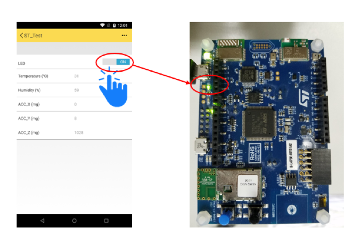
The user can also push the virtual button in mobile App to change the status of LED on the client board. The frequency of controlling the client board should not be more than 1 time per second because the reaction of the board may not catch up user's high frequency controlling due to network delay.
Figure 21. Cloud to Device message
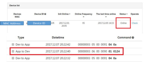
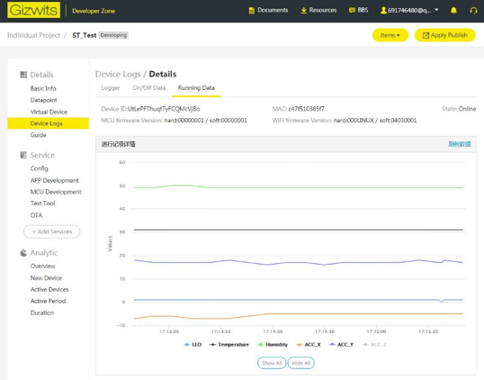
The sensor data and LED status are also visible on the GIZWITS WEB console
Figure 22. WEB Console
6.7 OTA
The network connectivity to GIZWITS cloud server allows the client board to download and run a new version of the firmware without connection to any development tool.
Here an example is given to illustrate how to upgrade a new firmware onto the client board.
The provided example is implemented for the STM32L4 Series, and relies on specific
capabilities of this core:
•Dual-boot from the dual-bank internal Flash memory, as detailed in the application note"STM32 microcontroller system memory boot mode"(AN2606) available at www.st.com and illustrated in this STM32Cube example:
STM32Cube_FW_L4_V1.6.0\Projects\STM32L476GDiscovery\Examples\FLASH\FLASH_DualBoot
• 2k-paged internal Flash memory
The example consists in :
• Downloading the new firmware binary through HTTP
• Flashing on-the-fly the downloaded payload to the other flash bank which is not running with the current application.
• After flashing, a reboot will be executed to switch the boot flash bank to the one which is just flashed with the new firmware.
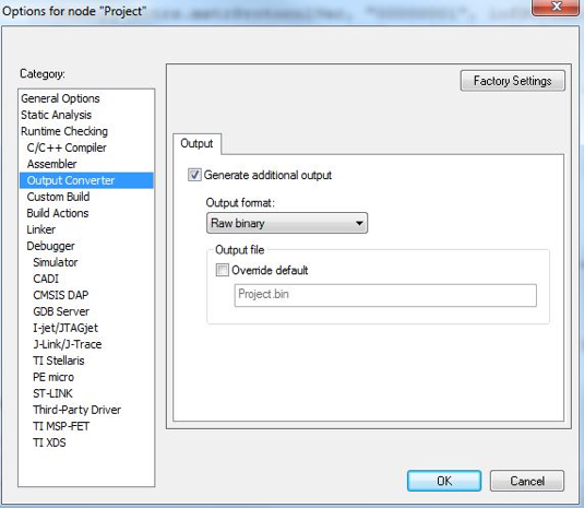
First, a new firmware is needed to be generated. In this case, format type of .bin file was chosen. In IAR, .bin file can be generated after project compilation if the following configuration is checked as Figure 23.
Figure 23. Configuration to generate bin file
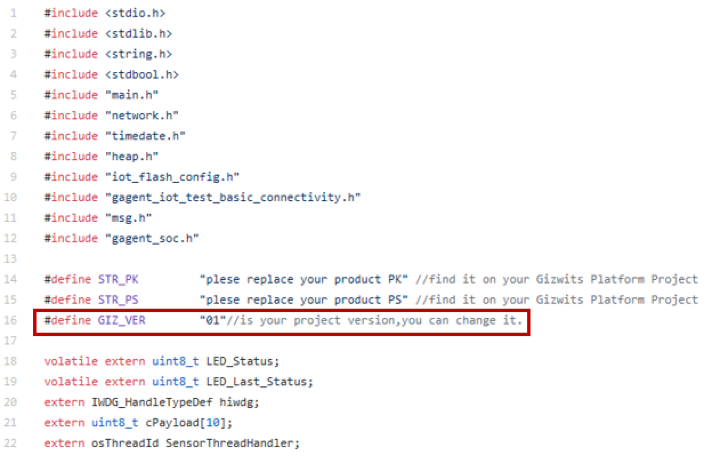
The version of software should be modified in the new firmware because the OTA will not be executed if the software version in cloud is lower than the one which is currently running in the client board. The software version includes 8 bits. The first 6 bits must be "040300", which is already defined in the project and can't be modified. However, the last 2 bits, which is defined as a macro "GIZ_VER" in the location of "\Projects\Common\Gizwits\Src\gagent_iot_test_basic_connectivity.c", showed in Figure 24, can be modified by the users. The range can be from "00" to "FF" in hex format so 255 choices are available. In this example, the currently running version is chosen as "04030001", and the new one which will be flashed to the client board contains the version of "04030002".
Figure 24. The 2 bits used to configure software version
Another point which should be noticed is that the flash mapping. The size of code section and data section (like the section to save the WIFI configuration and GIZWITS configuration) can' t exceed the range of any one flash bank (in this case, each flash bank has the size of 512K). For IAR, stm32l475xx_flash.icf, located at "Projects\B-L475E-IOT01\Applications\Cloud\Gizwits\EWARM" can be configured for flash mapping issue. For KEIL and SystemWorkbench (AC6), other files need to be modified.
- For KEIL, the file "Projects\B-L475E-IOT01\Applications\Cloud\Gizwits\MDK-ARM\B-L475E-IOT01\Exe\B-L475E-IOT01.sct" can be configured.
- For AC6, the file "Projects\B-L475E-IOT01\Applications\Cloud\Gizwits\SW4STM32\B-L475E-IOT01\STM32L475VGTx_FLASH.ld" can be configured.
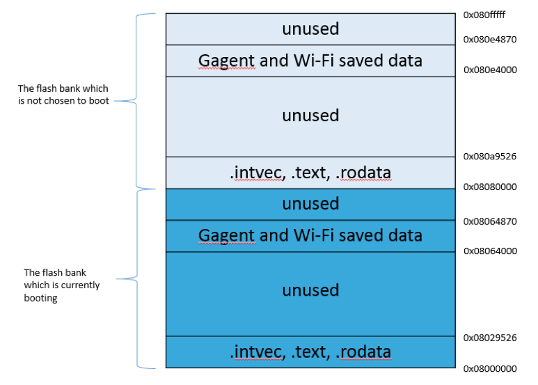
The program entry address of current running flash bank should normally be @ 0x08000000, and the start address for the other flash bank which is not chosen to boot should always be (0x08000000 + FLASH_BANK_SIZE), 0x08080000 in this case. For example, if the current booting bank is flash bank 2, the program will regard 0x08000000 as the start address of flash bank 2, and 0x08080000 as the start address of flash bank 1. The memory map diagram in this case is showed in Figure 25.
Figure 25. The memory map diagram in this example
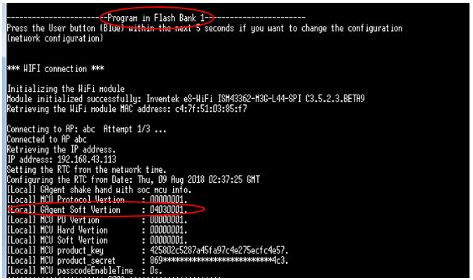
Run the application, at the beginning of debug information the booting flash bank can be seen, as Figure 26. In this case, flash bank 1 is firstly set as booting flash bank. Now the running software version should be "04030001".
Find the bin file at "Projects\B-L475E-IOT01\Applications\Cloud\Gizwits\EWARM\B-L475E-IOT01\Exe\Project.bin", whose version should be modified before and assigned as "04030002". Rename it (or just leave it alone) as Project_2_IAR.bin for example.
Figure 26. The beginning of debug information
Open the OTA panel in GIZWITS official website and edit the OTA information, as Figure 27. The new firmware should be uploaded.
Figure 27. Edit OTA information at GIZWITS webpage

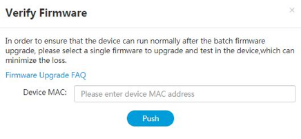
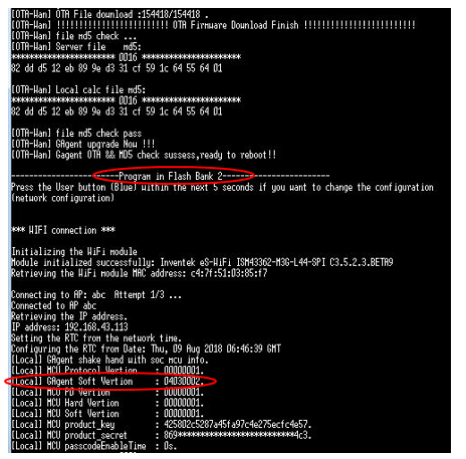
Enter the MAC address of the board and then click "Push" button. The program running on the board will automatically download the firmware from the server. After the whole firmware has been downloaded and written to the spare flash bank (flash bank 2 in this case), the board will automatically reboot, and showed the information as Figure 28. This time, flash bank 2 is the booting bank, with software version "04030002".
Figure 28. Debug information after OTA downloading and rebooting
Then a message on the webpage appear to inform the user the upgrading has been completed, as Figure 29.
Figure 29. Message on the webpage after upgrading
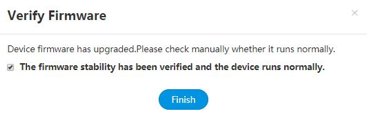
After clicking on the button "Finish", the firmware on the cloud can be trusted, and it is possible to push new firmware to more devices for the user.
In order to minimize the RAM footprint without relying on a local storage, the firmware file is downloaded through ranged HTTP requests. Record after record, the program data are retrieved in chunks, and immediately written to their destination Flash page.
Whenever the download session is interrupted, the application could resume the download without having to download again from the beginning of the file.
A checksum of all the received data is kept updated during this process.
Once the whole firmware has been received and programmed (that is when the end record is received), the application compares the computed checksum with the checksum read from the end record of the file.
Finally, the new firmware is running in flash bank 2, in this case. That means both flash banks have firmware. The user can manually set or reset the BFB2 option byte bit to switch the booting bank to either of the two flash bank, by code editing using the API _FLASH_set_boot_bank_() or by STM32 ST-LINK Utility which is a free software in www.st.com. The configuration in STM32 ST-LINK Utility is showed in Figure 15 in section of 6.4.
For more information about dual flash bank booting, See application note "STM32 microcontroller system memory boot mode" (AN2606) available at www.st.com.
Booting to the first bank can be obtained by resetting the BFB2 option byte flag, or by
erasing the 0x08080000 page in the STM32 ST-LINK utility.
6.8 Useful APIs for developer
The client board can upload data to the cloud and mobile App, and also receive the command sent from App to make some actions.
For uploading data to mobile App, API gagentUploadData() can be used. An example has been given in "\Projects\Common\Gizwits\Src\sensors_data.c".
For dealing with the command sent from App, API gizIssuedProcess() can be used. An example has been given in "\Projects\Common\Gizwits\Src\gagent_iot_test_basic_connectivity.c".
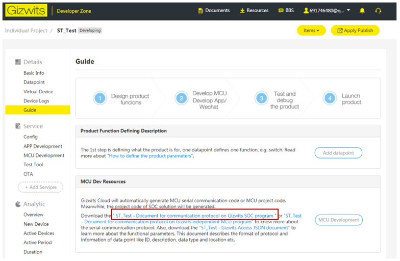
All the communication must comply with GIZWITS defined protocol, which can be found in the document "XXX (product name) - Document for communication protocol on Gizwits SOC program" in the location showed in Figure 30.
Figure 30. The location of GIZWITS communicating protocol document
7.Frequently ask edquestions
Q: Why do I get this pop-up(refer to Figure 31) when I open the project with IAR™?
Figure 31. Pop-up when the IAR™ IDE version is not compatible with the one used for I-CUBE-GIZWITS
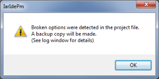
A: It is very likely that the IAR™ IDE version is older than the one used to develop the package (refer to the release note available in the package root folder for the IDE versions supported), hence the compatibility is not ensured. In this case, the IAR™ IDE version needs to be updated.
Q: My device does not connect to the Wi-Fi® access point. How shall I proceed?
A: Make sure that another device can connect to the Wi-Fi® access point. If it can, enter the Wi-Fi® credentials by pressing the user button (blue) up to five seconds after board reset.
Q: The proximity sensor always reports “8190” even if I place an obstacle close to it.
A: Make sure that the liner (which is a very thin film placed on the proximity sensor) has been removed. Its color is orange and it is not very visible.
8.Revision history
Table 2. Document revision history
| Date |
Revision |
Changes |
| 8-Dec-2017 |
1 |
Initial release. |
| 6-Sep-2018 |
2 |
Support for FOTA and device pre-authorization |